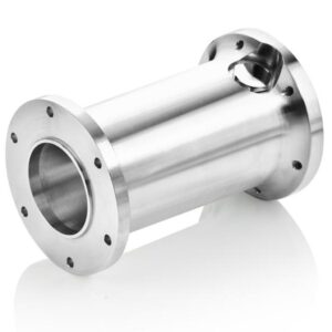
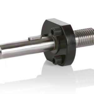
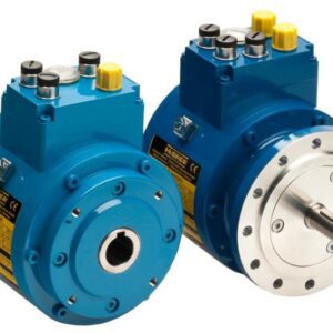
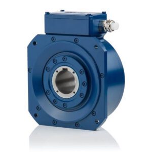
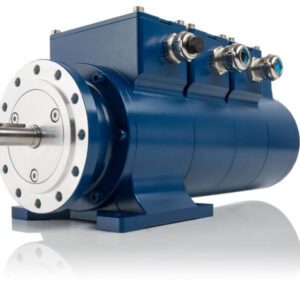
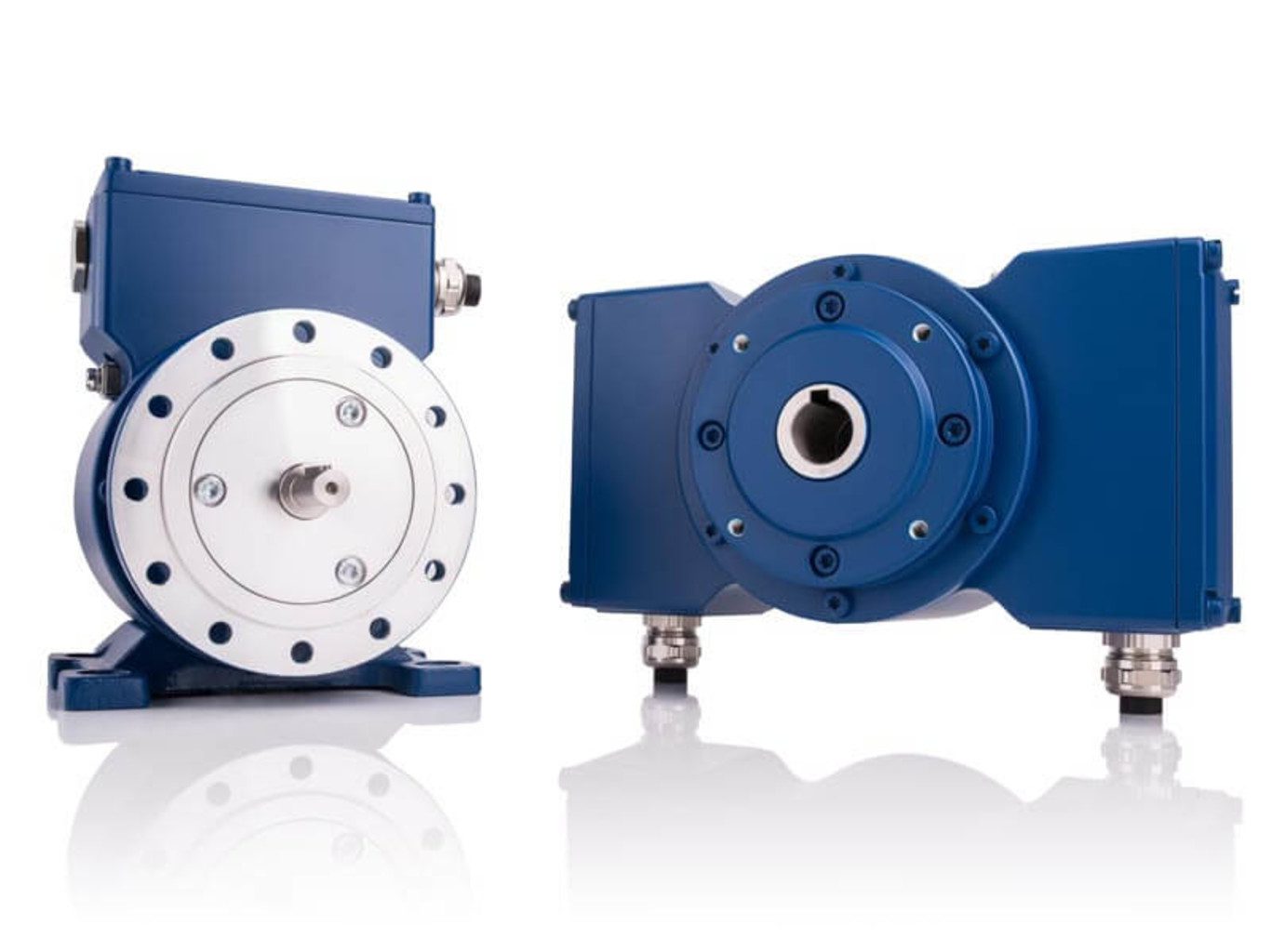
FG 40 / FGH(J) 40 Incremental Rotary Encoders Heavy-duty

Description

FG 40 / FGH(J) 40

Incremental rotary encoders for heavy duty applications

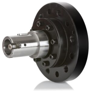
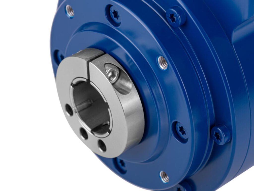
  • Hollow shafts up to Ø 25 mm, solid shafts up to Ø 14 mm (flange or foot mounting)
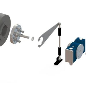
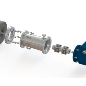
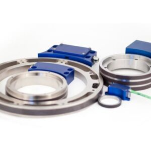
  • Robust design, other encoder can be attached
  • Up to 1 million pulses HTL / TTL, up to 2500 sine periods
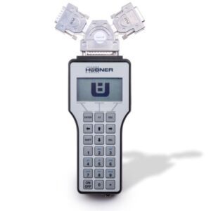
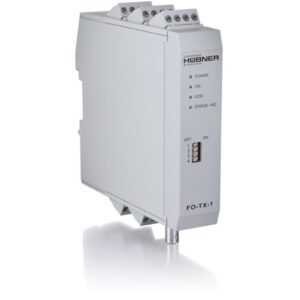
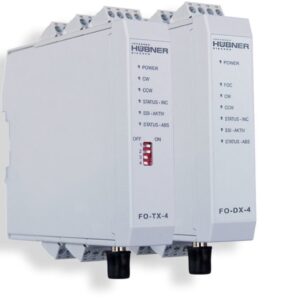
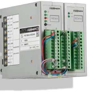
  • Options: Second signal output, FOC transmitter, programmable overspeed switches, hybrid bearings (FGHJ 40), hollow shafts in inch sizes

Incremental encoders Overspeed switches

Incremental rotary encoders for heavy industry

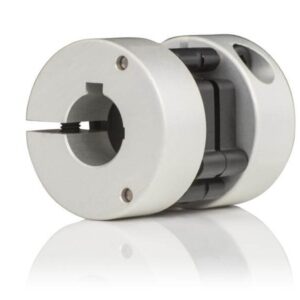
The incremental encoder FG 40 (solid shaft) / FGH (J) 40 (hollow shaft) can be deployed in a wide variety of applications to measure the speed of standard, auxiliary and secondary drives in steel and rolling mills, in mining operations as well as in ports and crane systems. When attaching with an isolated coupling (solid shaft) or with optionally available isolating hybrid bearings (hollow shaft) they protect the drivetrain against damaging shaft currents. They offer a high signal quality and, if required, a high pulse rate for dynamic feed-back control across the entire speed range. In particular the rugged foot construction facilitates simple attachment of further encoders at the second shaft end.

FG 40 / FGH(J) 40 Incremental Rotary Encoders Heavy-duty

Technical Data


Supply voltage 12-30 VDC (5 VDC optional)
Signal amplitude
  • HTL or TTL
  • Sin/Cos
Pulse rate
  • Standard pulse rates HTL/TTL: 500, 600, 1000, 1024, 1200, 1300, 2000, 2048, 2400, 2500
  • Special pulse rates HTL/TTL: 4000, 4096, 4800, 5000, 8192, 10000, 12000, 16000, 16384, 20000, 25000, 40000, 50000 up to 1 million
  • Standard pulse rates Sin/Cos: 500, 600, 1000, 1024, 1200, 1300, 2500
Output signals 0°, 90°, N, status and inverted signals
Maximum frequency
  • Solid shaft: up to 6000 rpm / 200 kHz
  • Hollow shaft: up to 4000 rpm / 200 kHz
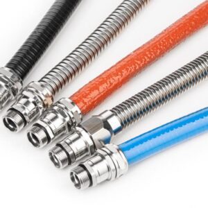
Electrical connection
  • Terminal strip in a terminal box
  • Fixed cable
  • 12-pole round connector Burndy
  • 15-pole industrial connector
  • FOC connector in a terminal box
Construction type / Ø shafts
  • Solid shaft (B5, B35) / Ø 11 mm, Ø 14 mm with feather key
  • Through hollow shaft / Ø 16 mm, Ø 19 mm, Ø 20 mm with keyway; Ø 16 mm, Ø 25 mm without keyway with clamp
  • Blind hollow shaft in inches / Ø 3/8“, Ø 1/2“, Ø 5/8“, Ø 3/4“, Ø 7/8“, Ø 1“ with clamping ring
Device temperature range
  • 0 °C to +70 °C
  • -25 °C to +85 °C
  • -40 °C to +85 °C
  • -5 °C to +100 °C
Degree of protection Up to IP66 / IP67
Weight Approx. 3.5 kg
Device options
  • Redundant incremental output
  • S: Electronic overspeed switch with two mutually independent, programmable switching points.
  • FOC: As an alternative to conventional signal transmissions via copper cables it is also possible to transmit encoder signals via a fiber optic cable.
  • N: Mechanically fixed reference pulse (N), one square-wave pulse per revolution, with inverted signal.
  • 2F: Twice as many basic track pulses by combining the 0° and 90° tracks.
  • B: Rapid direction of rotation sensing at each edge of 0° and 90° tracks.
  • B2: Rapid direction of rotation sensing at each edge of 0° and 90° tracks; additional standstill detection.
  • B3: Direction of rotation dependent output signals. This option supports counter cards with separate UP/DOWN pulse inputs. Basic track signals are issued at optional output 1 when rotation is clockwise and at optional output 2 when rotation is counterclockwise.
  • SH: 1 Vpp signals sin, cos, reference pulse. Status as HTL signal; all signals each with respective inverted signals.
  • ST: 1 Vpp signals sin, cos, reference pulse. Status as TTL signal; all signals each with respective inverted signals.
Mechanical options
  • Second shaft end with B14 flange for attachments (solid shaft construction type only)
  • Additional foot (solid shaft construction type only)
  • Isolated ball bearing (hollow shaft construction type only)
  • MI: Saliferous environment
  • MS: Wet areas in rolling mills
  • Hollow shaft devices: Torque bracket (on request)
Special features and certificates UL/CSA

Downloads


FG(HJ) 40 / 40 Ex / 41 / INOX (de/en)
Catalogs


Simplifying Cranes (de/en)
Catalogs


FGHJ 40 inch dimension shafts (en)
Flyer New


FG… (en)
Inquiry forms


FG 40 (en)
Operating and assembly instructions


FGH(J) 40 (en)
Operating and assembly instructions


FG / FGH(J) / 2 / 40 (de/en)
EC declaration of incorporation


UL / CSA (de/en)
Certificate