Description
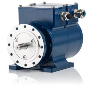
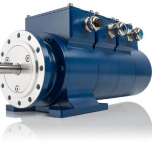
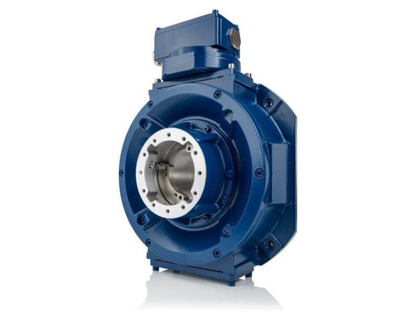
FGH 8
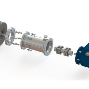
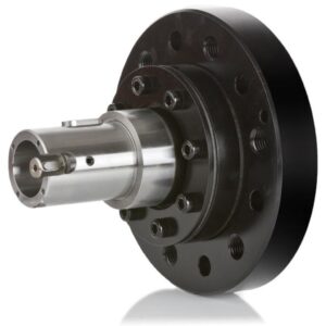
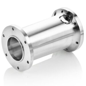
Optical rotary encoders with hollow shaft up to 80 mm
- Hollow shafts up to Ø 80 mm
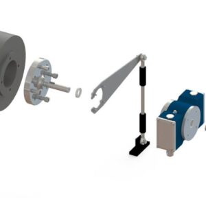
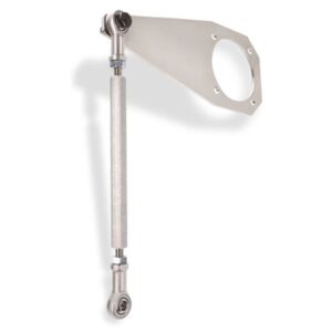
- B14 flange as basis to attach 3 more devices
- Up to 4096 pulses HTL / TTL
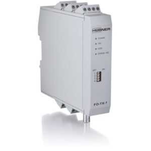
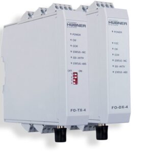
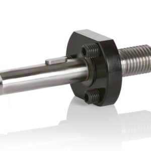
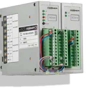
- Options: Second signal output, FOC transmitter, overspeed switch, further signal options, isolation sleeve
![]()
![]()


Optical rotary encoders for main drives
The incremental encoders FGH 8 for continuous hollow shafts up to Ø 80 mm are mostly mounted on the unused shaft end by means of an isolated adapter flange or directly onto the shaft. Thanks to the flat design they are ideally suitable for attaching further sensors such as speed switches, absolute encoders or combinations of these. Furthermore, there is also the option of a redundant configuration with two equal scanning systems and evaluation electronics. That increases safety or facilitates the provision of separate signals to the motor controls and a higher-level controller.

Technical Data
| Supply voltage | 12-30 VDC (Option 5 VDC) |
| Signal amplitude | HTL or TTL |
| Pulse rate | 600, 720, 750, 1000, 1024, 1200, 2048, 2560, 2800, 4096 |
| Output signals | 0° track |
| Maximum frequency | Hollow shaft: up to 3000 rpm (up to 1200 rpm with IP66) / max. 100 kHz |
| Electrical connection |
|
| Construction type / Ø shafts | Hollow shaft / up to Ø 80 mm with feather key |
| Device temperature range | -25 °C to +85 °C |
| Degree of protection | Up to IP66 |
| Weight | Approx. 13 kg |
| Device options |
|
| Mechanical options |
|
| Special features and certificates |
Downloads